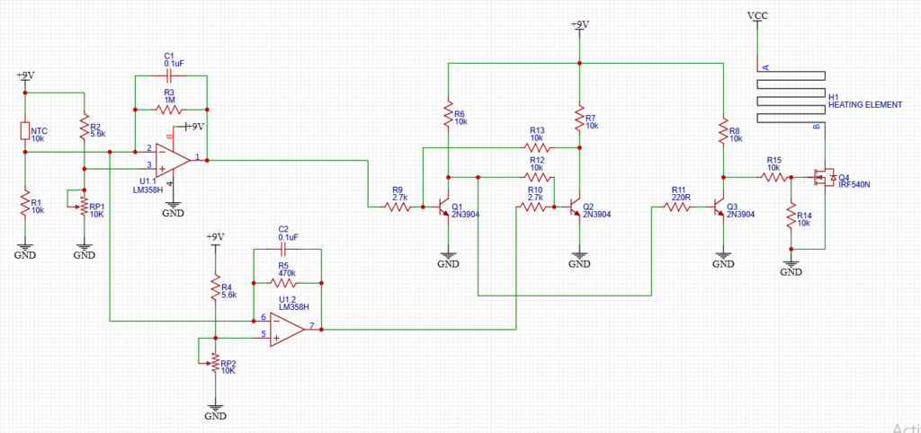
Automatic temperature control is essential in many DIY and real-world applications — from automotive heating and battery warmers to incubators and frost protection systems. In this guide, we’ll explore a temperature controlled heater circuit built around an LM358 dual op-amp, a 10 kΩ NTC thermistor, and a powerful IRF540N MOSFET.
This circuit automatically turns a heating element ON when temperature drops and switches it OFF when the desired temperature is reached, with built-in hysteresis to prevent unstable flickering.
Whether you’re a hobbyist or builder, this project offers a reliable and adjustable thermostat solution.
1. Temperature Sensing Stage
A 10 kΩ NTC thermistor and R1 (10 kΩ) form a voltage divider powered from 9 V.
An NTC thermistor changes resistance with temperature:
- Cold → higher resistance
- Warm → lower resistance
This produces a voltage proportional to temperature, which is used as the control signal.
2. Dual Comparator Stage (LM358)
The LM358 contains two op-amps configured as comparators:
Low Temperature Comparator
Detects when temperature drops below a set threshold and commands the heater to turn ON.
High Temperature Comparator
Detects when temperature exceeds a second threshold and switches the heater OFF.
Feedback components introduce hysteresis, preventing rapid toggling near the threshold.
3. Transistor Logic Stage
Q1 and Q2 are wired with cross-coupling resistors, which creates a simple bistable latch.When Q1 turns ON, it pulls its collector voltage low. Through the coupling resistor, this low voltage removes base drive from Q2, forcing Q2 OFF. Because Q2 is OFF, it cannot oppose Q1, so Q1 remains ON. The circuit is now stable in this state.
When the high-temperature comparator activates, it drives Q2 instead. Q2 turns ON and pulls its collector low. This removes base drive from Q1, turning Q1 OFF. Again, the cross-coupling ensures the state is reinforced. The circuit stays in this new condition until another valid trigger occurs. This behavior is why the pair is called a bistable latch — it has two stable states and “remembers” which one it is in.
Q3 acts as an inverter and driver between the latch and the MOSFET. It is wired as a common-emitter switch. When the latch output provides base current to Q3, Q3 turns ON and pulls its collector low. When the latch output is low, Q3 turns OFF and its collector rises high through a resistor. This means the signal leaving Q3 is the opposite polarity of the latch signal.
The inversion is useful because the MOSFET gate needs a clear, strong control voltage. Q3 isolates the latch from the power stage and ensures the MOSFET receives a decisive ON or OFF drive rather than a weak or noisy signal.
Putting it all together, when temperature falls below the low threshold, the comparator activates Q1. The latch locks into the heater-ON state. Q3 then drives the MOSFET so the heater receives power. When temperature rises above the high threshold, Q2 is activated instead. The latch flips to the heater-OFF state, Q3 changes output, and the MOSFET disconnects the heater.
4. Power Switching Stage — IRF540N MOSFET
The IRF540N MOSFET acts as a high-current electronic switch
The MOSFET can handle significant current when properly heatsinked.
How to Set Low and High Temperature Thresholds
The thermistor divider voltage determines switching points. By adjusting the comparator reference potentiometers, you select the ON/OFF temperatures.
Temperature vs Voltage Calibration Table
(Approximate values for a typical 10 kΩ NTC, β ≈ 3950, 9 V supply)
| Temp (°C) | Thermistor Resistance | Sense Voltage |
|---|---|---|
| 0 | 33.6 kΩ | 2.06 V |
| 5 | 25.9 kΩ | 2.51 V |
| 10 | 20.2 kΩ | 2.98 V |
| 15 | 15.8 kΩ | 3.48 V |
| 20 | 12.5 kΩ | 3.99 V |
| 25 | 10.0 kΩ | 4.50 V |
| 30 | 8.0 kΩ | 4.99 V |
| 35 | 6.5 kΩ | 5.45 V |
| 40 | 5.3 kΩ | 5.88 V |
| 45 | 4.3 kΩ | 6.27 V |
| 50 | 3.6 kΩ | 6.62 V |
Example calibration
Want heater ON at 5 °C and OFF at 20 °C:
- Set low threshold ≈ 2.5 V
- Set high threshold ≈ 4.0 V
Use a multimeter to measure the sensing node while adjusting the potentiometers.
Practical Calibration Tips
- Let temperature stabilize before adjusting
- Avoid touching the thermistor (body heat affects readings)
- Use a thermometer for accurate setup
- Test switching behavior slowly
Advantages of This Circuit
- Adjustable temperature window
- Stable hysteresis control
- Noise-resistant switching
- High-current heater capability
- Simple, affordable components
- Suitable for automotive or DIY projects
Applications
This thermostat circuit is ideal for:
- Automotive window heaters
- Battery warming systems
- Incubators
- Frost protection
- Environmental temperature control
- DIY smart heating projects
Design Considerations
- Add supply filtering in noisy environments
- Heatsink the MOSFET for high loads
- Place thermistor close to sensing area
- Use proper wiring for heater current
Final Thoughts
This LM358 temperature controlled heater circuit provides a dependable and adjustable thermostat solution using widely available components. The addition of hysteresis and a MOSFET power stage makes it robust enough for practical heating control.
With proper calibration, it becomes a versatile DIY temperature controller suitable for many real-world applications.