The NE555 timer IC is famous for its flexibility, and one of its most useful applications is PWM dimming. The circuit shown here is a 12V LED dimmer built around a 555 timer that produces pulse-width modulation (PWM) to control brightness efficiently.
Unlike simple resistor dimming, PWM adjusts brightness without wasting power, making it ideal for LEDs.
In this article, we’ll break down:
- How the dimmer circuit works
- Why the diode network is important
- How brightness control is achieved
- What each component does
- Practical improvements and applications
What This Circuit Does
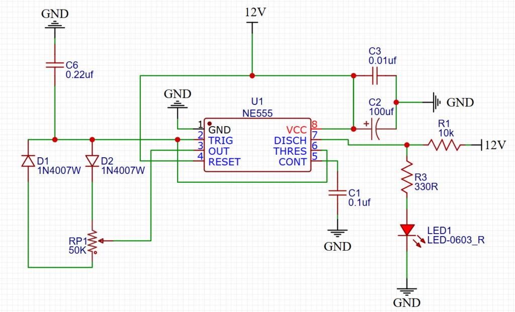
This circuit generates a PWM (Pulse Width Modulation) signal using a 555 timer in astable mode. The duty cycle — how long the signal stays ON vs OFF — is adjustable using a potentiometer.
Changing duty cycle changes the average power delivered to the LED:
- Longer ON time → brighter LED
- Shorter ON time → dimmer LED
The switching is fast enough that the eye perceives smooth brightness control.
Core Working Principle
The 555 timer repeatedly:
- Charges a timing capacitor
- Discharges it
- Switches output state
This cycle creates a square wave that drives the LED.
The key feature of this circuit is that charging and discharging paths are separated using two diodes. This allows independent control of ON time and OFF time.
That’s what enables smooth dimming instead of just changing blinking speed.
Timing Network — The Heart of the Dimmer
RP1 (50k Potentiometer)
This is the brightness control knob.
Turning the pot changes how current flows during capacitor charging and discharging, which alters the PWM duty cycle.
D1 and D2 — Direction Control Diodes
These diodes create separate paths:
- One path controls capacitor charging
- The other controls discharging
Because of this:
- One half of the potentiometer affects ON time
- The other half affects OFF time
This gives a wide dimming range while keeping frequency relatively stable — preventing visible flicker.
C6 — Timing Capacitor
This capacitor determines oscillation speed.
Smaller value → faster PWM frequency
Larger value → slower PWM frequency
The chosen value provides flicker-free dimming suitable for LEDs.
555 Timer Operation in This Circuit
Inside the 555:
- Capacitor voltage is compared to internal reference levels
- When thresholds are crossed, output toggles
- Discharge transistor resets the cycle
This repeating charge/discharge process creates PWM.
The output drives the LED through a resistor.
Output Stage — LED Drive
R3 (330Ω)
Limits LED current to protect it.
LED
Displays brightness proportional to PWM duty cycle.
Even though the LED is switching rapidly, your eyes see continuous brightness variation.
Stability Components
C1 (Control Voltage Filter)
Reduces noise and stabilizes internal thresholds.
C2 + C3 (Supply Filtering)
Smooth the 12V supply to prevent erratic behavior or jitter in PWM.
This improves dimming smoothness.
Practical Applications
This simple dimmer circuit can be used for:
- LED brightness control
- Panel lighting
- Automotive interior lights
- DIY lighting projects
- Learning PWM fundamentals
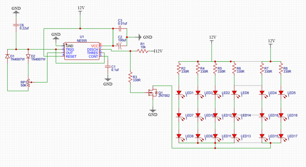
With a transistor or MOSFET stage added, it can control higher power loads.
Customization Ideas
- Adding a MOSFET for high-current LEDs
- Driving motors or fans with proper power stages
Beginner Build Tips
- Observe diode polarity carefully
- Use a regulated 12V supply
- Keep wiring short to reduce noise
- Double-check capacitor polarity
Conclusion
This NE555 PWM dimmer circuit is a smart and efficient way to control LED brightness. The diode-split timing network allows smooth duty cycle control while maintaining stable oscillation — a clever use of the classic 555 timer.
It’s an excellent beginner project and a foundation for more advanced PWM control designs.